Micropile Underpinning of a Historic Structure – Support for the Next 100 Years
By Mike Walker, PE, PENG, DGE, Senior Principal, GEI Consultants, Inc. and Eleanor F. Bloom, PE, Project Engineer, GEI Consultants, Inc.
Posted
in
Featured Projects


Alliant Energy owns and operates the Prairie Du Sac Hydroelectric Project located in Prairie du Sac, Wisconsin. The original dam was constructed in 1914 and is the last dam on the Wisconsin River. The Project includes the east embankment, a gated spillway with 41 radial tainter gates, an abandoned navigation lock, and a powerhouse at the right/west abutment. The Project operates as a run-of-the-river facility, with eight generating units and a total rated capacity of 31 MW. The normal maximum reservoir level is El. 774.4 feet, and normal tailwater elevations fluctuate between 730.4 feet and 732.4 feet depending on river flows.
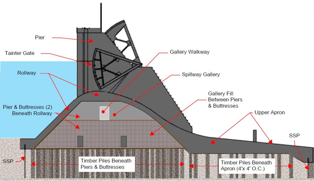
The spillway is a hollow, Ambursen style (slab and buttress) concrete structure supported on vertically driven timber piles bearing in sandy alluvium. A cross section of the spillway is depicted in Figure 1. The spillway is 1,010 feet long with 41 tainter gates. The gates rest on an ogee rollway slab. A continuous upstream steel sheet pile seepage cutoff wall is present along the heel.
The entire spillway section and concrete aprons downstream of the spillway are supported on a grid of vertically driven timber piles steel sheet pile seepage cutoff walls. There are approximately 4,200 timber piles supporting the spillway, and 1,650 timber piles supporting the downstream concrete aprons. The timber piles are of mixed species and were driven 20 to 35 feet into the sandy alluvial deposits.
Since construction, the tailwater level has dropped approximately 10 to 12 feet. This has caused a considerable number of the timber piles to become exposed to wet-dry cycles resulting in their deterioration. Investigations performed in the 1980s indicate that the timber piles are in varying stages of deterioration (some missing) and will eventually fail to support the structure. Without remediation, continued pile deterioration could result in significant differential settlement, concrete cracking, and gate binding.

Cross section of the Prairie du Sac Spillway.
I. Design Challenges and Solutions
Alliant contracted the design-build team of GEI Consultants, Inc., and Nicholson Construction Company (NCC) to design and construct a permanent structural underpinning solution to the slowly deteriorating timber pile foundations. The design consists of new high modulus micropiles and reinforced concrete transfer beams that, coupled with the inherent rigidity of the buttress and slab structure, allow the slow transfer of load from rotting timber piles in a manner that minimizes the risk of dam movement and future distress. The micropile underpinning system was chosen for its simplicity, high load capacity and proven reliability of structural underpinning using low risk drilling methods.
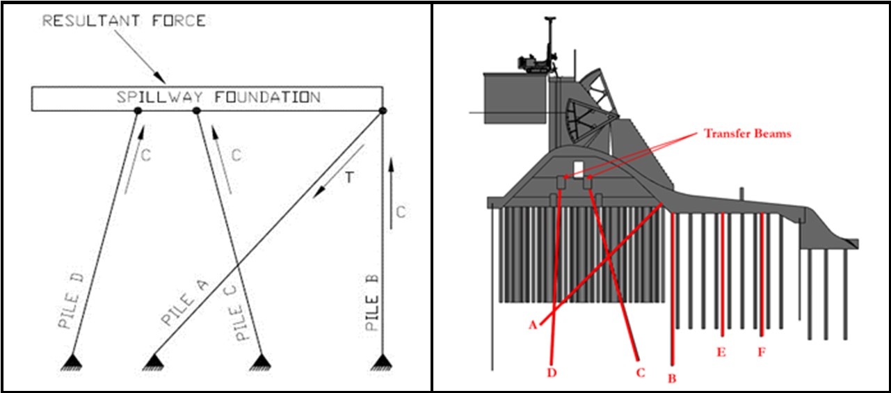
The spillway underpinning design included 981 high-modulus micropiles. The micropiles were designed to carry all the water and gravity loads imposed on the dam without the benefit of the existing timber piles or the downstream spillway aprons. The resultant force is transmitted through the spillway structure (slabs, piers, buttresses, and transfer beams) to the tension micropiles (A-micropiles) and compression micropiles (B, C, and D-micropiles). The simple free-body diagram showing this load transfer concept versus the final micropile layout is shown in Figure 2. To minimize lateral loads on the micropiles that could lead to additional movement, the A, B, C and D micropiles form a truss frame that allows loads to be efficiently transferred to the micropiles as axial compression and tension loads. Two rows of vertical micropiles, the E and F micropiles, were also constructed to independently support the upper concrete apron slab.
As the wood piles continue to lose capacity with time in a non-uniform manner and cause small localized concrete dam settlements, the stiffer, high-modulus micropiles, along with the remaining timber piles, will accept the load proportional to their relative stiffness and distance from the deteriorated timber pile. The displacement resulting from the loss of any single deteriorated pile will generally take place gradually and be extremely small as its load is distributed over all remaining, functioning timber piles and new micropiles. This transfer of load as the wood piles decay will result in effectively very little differential movement (e.g., less than 0.002-inch distortion) and an imperceptible total movement of the structure.
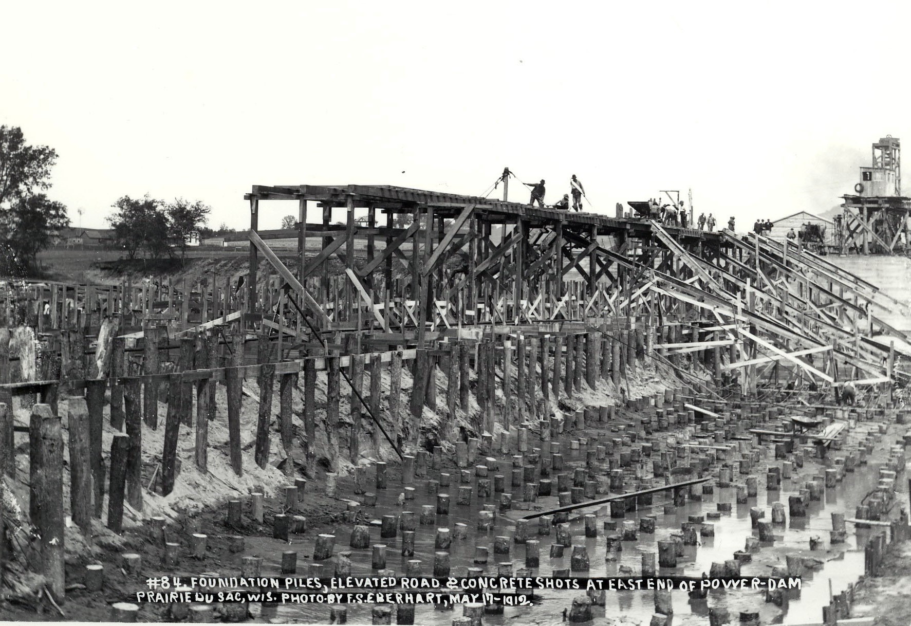
Historic photographs depict the many potential obstructions below the spillway and apron structure, including a forest of timber piles and steel sheeting (Figure 3). To avoid interferences, the micropiles were required to be installed in the open spaces between the existing piers and buttresses. The design incorporated contingencies for micropile offsets and supplemental micropiles should obstructions be encountered at design locations. The structural design sensitivity analysis showed where certain micropiles could be omitted in a worst-case scenario when obstructions made micropile installation impossible.
The load distribution to micropiles and interaction with the transfer beams were estimated using three- and five-bay three-dimensional finite element modeling analysis methods. The finite element model was used to evaluate the spillway structure for each of the design load cases and to confirm the foundation remediation system elements were not overstressed. In addition, the finite element model was used to run sensitivity analyses to evaluate the overall system should installation of individual micropile members not meet specifications.

Truss frame load transfer concept (left) versus final micropile layout
shown superimposed over the spillway section (right).
shown superimposed over the spillway section (right).
II. Construction Challenges and Solutions
The permanent underpinning solution was constructed over three construction seasons (approximately May to December) from 2018 to 2020. NCC advanced the micropile steel pipe casing to target depths using duplex drill methods. After drill rod extraction, neat cement grout was placed using tremie grout pipes. Threaded reinforcing bar was lowered into the micropile casing, and the casing sections were extracted. The casing was left in place through the loose soil in the upper portion of the B-, C-, D-, E- and F-micropiles to provide shear and moment capacity. The permanent casing was removed from the A micropiles design since the A-micropiles are in tension and do not rely on the casing for lateral support.
Occasionally, obstructions were encountered that prevented the micropiles from reaching their target depths. Of the 981 designed micropiles, only eight micropiles could not be installed. When impenetrable obstructions were encountered, A-, B-, E-, and F-micropiles could be relocated up to 12-inches from their design location. Obstructions prevented the installation of five C-and D-micropiles over three bays. After additional analysis, GEI determined that only two supplemental D-micropiles slightly offset from the design location were required to meet the design intent.

Historic photo showing original timber piles from 1914 construction.
III. Conclusions
The Spillway Foundation Remediation Project was one of the largest dam foundation micropile underpinning project performed and will extend the life of this 107-year-old structure another 100-years. The design-build procurement process worked well on this project by enabling expedited adjustments to design due to conditions encountered during construction. The project was completed on schedule thanks to the untiring effort and dedication to a successful project completion displayed by all parties.
